If you need urgent consulting help click here
STM32F030 DEMO BOARD
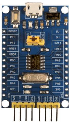
This board has the bare minimum components required to power on the STM32F030F4P6 MCU. Most of the GPIOs on the STM32 SoC have been exposed in the external headers with silk screen labels that match the SoC’s pin names.
For practical use, you’ll need to add additional components and circuits using a breadboard, for example.

More information about the board can be found at the stm32-base.org website 1.
More information about STM32F030F4P6 can be found here:
Hardware
STM32F030F4P6 ARM Cortex-M0 processor, frequency up to 48 MHz
16 KiB of flash memory and 4 KiB of RAM
8 MHz quartz crystal
1 user LED
One reset button
2-way jumper (BOOT0)
Serial (1x4 male dupont (2.54mm))
SWD (1x4 male dupont (2.54mm))
USB port (power only)
Supported Features
The Zephyr stm32f030_demo board configuration supports the following hardware features:
Interface |
Controller |
Driver/Component |
|---|---|---|
NVIC |
on-chip |
nested vector interrupt controller |
UART |
on-chip |
serial port |
PINMUX |
on-chip |
pinmux |
GPIO |
on-chip |
gpio |
WATCHDOG |
on-chip |
independent watchdog |
Other hardware features are not yet supported on this Zephyr porting.
The default configuration can be found in the defconfig file:
boards/arm/stm32f030_demo/stm32f030_demo_defconfig
Programming and Debugging
Applications for the stm32f030_demo board configuration can be built and
flashed in the usual way (see Building an Application and
Run an Application for more details).
Flashing
The board can be flashed by using ST-LINKV2 in-circuit debugger and programmer. This interface is supported by the openocd version included in the Zephyr SDK.
