If you need urgent consulting help click here
Laird Connectivity Pinnacle 100 DVK
Overview
The Pinnacle™ 100 cellular modem seamlessly incorporates a powerful Cortex M4F controller, full Bluetooth 5 and LTE-M/NB-IoT capabilities – all with full regulatory certifications and LTE carrier approvals. The Pinnacle 100 also delivers complete antenna flexibility, with pre-integrated internal or external antenna options such as the Revie Flex family of LTE and NB-IoT internal antennas.
Develop your application directly on the M4F controller using Zephyr RTOS to cut BOM costs and power consumption. Take advantage of the Zephyr community, Laird Connectivity’s sample code (cellular, Bluetooth) and hardware interfaces, or use our hosted mode AT commands set firmware.
Extremely power conscious, the Pinnacle 100 is ideal for battery-powered devices operating at the edge of your IoT networks, seamlessly bridging the cellular WAN to BLE. It’s never been easier to bridge wireless Bluetooth 5 sensor data to cloud services like AWS IoT over a low-power LTE connection.
More information about the board can be found at the Pinnacle 100 website 1.
The Pinnacle 100 Development Kit (453-00010-K1 or 453-00011-K1) hardware provides support for the Nordic Semiconductor nRF52840 ARM Cortex-M4F CPU, Sierra Wireless HL7800 3 (Altair ALT1250) and the following devices:
ADC
CLOCK
FLASH
GPIO
I2C
MPU
NVIC
PWM
RADIO (Bluetooth Low Energy and 802.15.4)
RTC
Segger RTT (RTT Console)
SPI
UART
USB
WDT
QSPI
BME680
HL7800

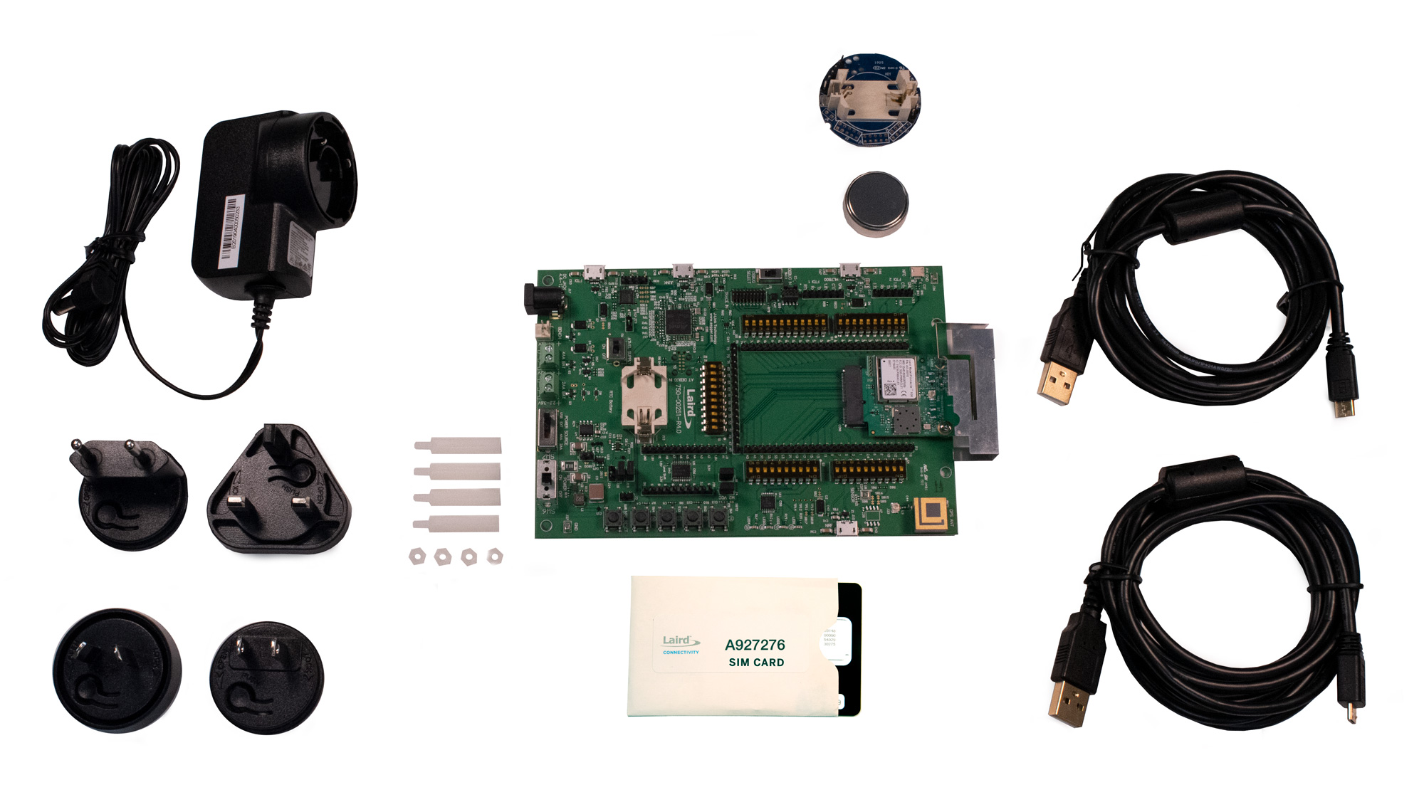
Fig. 147 Pinnacle 100 DVK (453-00010-K1)
Hardware
Supported Features
The Pinnacle 100 development board configuration supports the following hardware features:
Interface |
Controller |
Driver/Component |
|---|---|---|
ADC |
on-chip |
adc |
CLOCK |
on-chip |
clock_control |
FLASH |
on-chip |
flash |
GPIO |
on-chip |
gpio |
I2C(M) |
on-chip |
i2c |
MPU |
on-chip |
arch/arm |
NVIC |
on-chip |
arch/arm |
PWM |
on-chip |
pwm |
RADIO |
on-chip |
Bluetooth, ieee802154 |
RTC |
on-chip |
system clock |
RTT |
Segger |
console |
SPI(M/S) |
on-chip |
spi |
UART |
on-chip |
serial |
USB |
on-chip |
usb |
WDT |
on-chip |
watchdog |
QSPI |
on-chip |
qspi/MX25R64(8MB) |
BME680 |
I2C(M) |
sensor/bme680 |
HL7800 |
UART |
HL7800 modem driver |
See Pinnacle 100 website 1 for a complete list of Pinnacle 100 Development Kit hardware features.
Programming and Debugging
Applications for the pinnacle_100_dvk board configuration can be
built and flashed in the usual way. (see Building an Application
and Run an Application for more details)
Flashing
Follow the instructions in the Nordic nRF5x Segger J-Link page to install and configure all the necessary software. Further information can be found in Flashing. Then build and flash applications as usual (see Building an Application and Run an Application for more details).
Here is an example for the Hello World application.
First, run your favorite terminal program to listen for output.
Note
On the Pinnacle 100 development board, the FTDI USB should be used to access the UART console.
$ minicom -D <tty_device> -b 115200
Replace <tty_device> with the port where the board Pinnacle 100 DVK
can be found. For example, under Linux, /dev/ttyUSB0.
Then build and flash the application in the usual way.
# From the root of the zephyr repository
west build -b pinnacle_100_dvk samples/hello_world
west flash
Debugging
Refer to the Nordic nRF5x Segger J-Link page to learn about debugging Nordic boards with a Segger IC.
Software
Pinnacle 100 Out-of-Box Demo Software
The Pinnacle 100 development kit ships with an out of the box software demo. Check out the Pinnacle 100 OOB Demo 4 source code and documentation.
Sample Applications
Pinnacle 100 Sample Applications 5 are available.
Testing Bluetooth on the Pinnacle 100 DVK
Many of the Bluetooth examples will work on the Pinnacle 100 DVK. Try them out:
Testing the LEDs and buttons in the Pinnacle 100 DVK
There are 2 samples that allow you to test that the buttons (switches) and LEDs on the board are working properly with Zephyr:
samples/basic/blinky
samples/basic/button
You can build and flash the examples to make sure Zephyr is running correctly on your board. The button and LED definitions can be found in boards/arm/pinnacle_100_dvk/pinnacle_100_dvk.dts.
Selecting the pins
To select the pin numbers for tx-pin and rx-pin:
tx-pin = <pin_no>
Open the nRF52840 Product Specification 2, chapter 7 ‘Hardware and Layout’. In the table 7.1.1 ‘aQFN73 ball assignments’ select the pins marked ‘General purpose I/O’. Note that pins marked as ‘low frequency I/O only’ can only be used in under-10KHz applications. They are not suitable for 115200 speed of UART.
Translate the ‘Pin’ into number for devicetree by using the following formula:
pin_no = b\*32 + a
where a and b are from the Pin value in the table (Pb.a).
For example, for P0.1, pin_no = 1 and for P1.0, pin_no = 32.
