If you need urgent consulting help click here
NXP RDDRONE-FMUK66
Overview
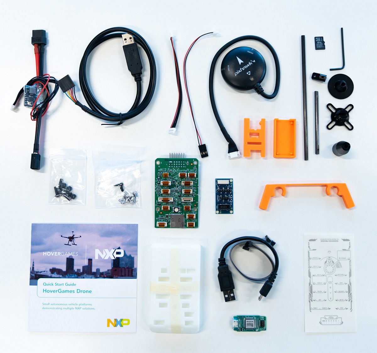
The RDDRONE FMUK66 is an drone control board with commonly used peripheral connectors and a Kinetis K66 on board.
Comes with a J-Link Edu Mini for programming and UART console.

Hardware
MK66FN2MOVLQ18 MCU (180 MHz, 2 MB flash memory, 256 KB RAM, low-power, crystal-less USB, and 144 Low profile Quad Flat Package (LQFP))
Dual role USB interface with micro-B USB connector
RGB LED
FXOS8700CQ accelerometer and magnetometer
FXAS21002CQ gyro
BMM150 magnetometer
ML3114A2 barometer
BMP280 barometer
Connector for PWM servo/motor controls
Connector for UART GPS/GLONASS
SDHC
For more information about the K64F SoC and FRDM-K64F board:
Supported Features
The rddrone-fmuk66 board configuration supports the following hardware features:
Interface |
Controller |
Driver/Component |
|---|---|---|
NVIC |
on-chip |
nested vector interrupt controller |
SYSTICK |
on-chip |
systick |
PINMUX |
on-chip |
pinmux |
GPIO |
on-chip |
gpio |
I2C |
on-chip |
i2c |
SPI |
on-chip |
spi |
WATCHDOG |
on-chip |
watchdog |
ADC |
on-chip |
adc |
DAC |
on-chip |
dac |
PWM |
on-chip |
pwm |
ETHERNET |
on-chip |
ethernet |
UART |
on-chip |
serial port-polling; serial port-interrupt |
FLASH |
on-chip |
soc flash |
USB |
on-chip |
USB device |
CAN |
on-chip |
can |
RTC |
on-chip |
rtc |
DMA |
on-chip |
dma |
The default configuration can be found in the defconfig file:
boards/arm/rddrone_fmuk66/rddrone_fmuk66_defconfig
Other hardware features are not currently supported by the port.
System Clock
The K66F SoC is configured to use the 16 MHz external oscillator on the board with the on-chip PLL to generate a 160 MHz system clock.
Serial Port
The K66F SoC has six UARTs. LPUART0 is configured for the console, UART0 is labeled Serial 2, UART2 is labeled GPS, UART4 is labeled Serial 1. Any of these UARTs may be used as the console by overlaying the board device tree.
USB
The K66F SoC has a USB OTG (USBOTG) controller that supports both device and host functions through its micro USB connector (K66F USB). Only USB device function is supported in Zephyr at the moment.
Programming and Debugging
Build and flash applications as usual (see Building an Application and Run an Application for more details).
Configuring a Debug Probe
A debug probe is used for both flashing and debugging the board. This board is configured by default to use jlink. The board package with accessories comes with a jlink mini edu and cable specifically for this board along with a usb to uart that connects directly to the jlink mini edu. This is the expected default configuration for programming and getting a console.
# From the root of the zephyr repository
west build -b rddrone-fmuk66 samples/hello_world
Configuring a Console
Use the following settings with your serial terminal of choice (minicom, putty, etc.):
Speed: 115200
Data: 8 bits
Parity: None
Stop bits: 1
Flashing
Here is an example for the Hello World application.
# From the root of the zephyr repository
west build -b rddrone-fmuk66 samples/hello_world
west flash
Open a serial terminal, reset the board (press the SW1 button), and you should see the following message in the terminal:
***** Booting Zephyr OS v2.7.0 *****
Hello World! rddrone-fmuk66
Debugging
Here is an example for the Hello World application.
# From the root of the zephyr repository
west build -b rddrone-fmuk66 samples/hello_world
west debug
Open a serial terminal, step through the application in your debugger, and you should see the following message in the terminal:
***** Booting Zephyr OS v2.7.0 *****
Hello World! rddrone-fmuk66
https://nxp.gitbook.io/hovergames/userguide/getting-started
https://www.nxp.com/webapp/Download?colCode=SPF-39053
https://www.nxp.com/docs/en/data-sheet/K66P144M180SF5V2.pdf
https://www.nxp.com/webapp/Download?colCode=K66P144M180SF5RMV2
